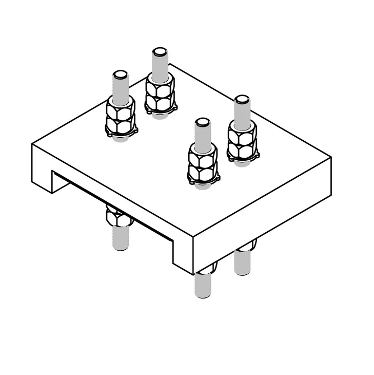
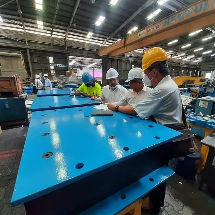
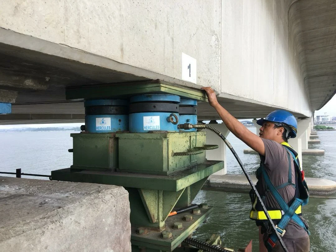
Hercules Expansion Joint (EJ)
Expansion Joint
Hercules Expansion Joint (EJ)
Hercules Engineering single element joints are used where a robust, water-tight expansion joint is required in highway bridges, parking stations, access ramps and a variety of other applications. Our Engineers are available at both design and construction stages to assist with the design and installation details of the joints.

Design Features
Types & Series: Single Element Series 13
The series 13 joints are fabricated from steel angles or blades and supplied in two main anchorage configurations depending on whether they are required for heavy or light traffic.
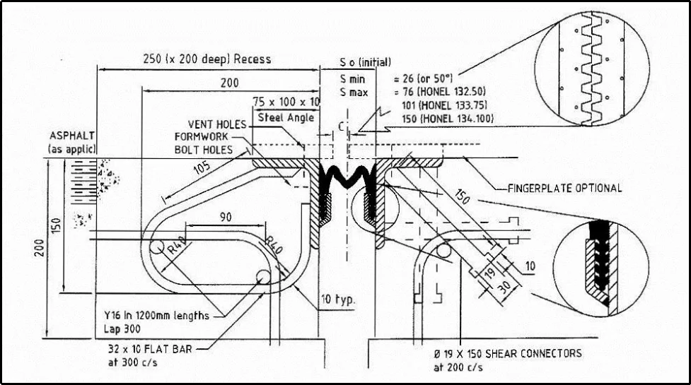
| Hercules Part No. | Total Movement (mm) | Transverse Movement (mm) | Vertical Movement (mm) | Smin (mm) | Smax (mm) |
|---|---|---|---|---|---|
| 132.50 | 50(±25) | ±30 | ±30 | 26 | 76 |
| 133.75 | 75(±35) | ±35 | ±35 | 26 | 101 |
| 134.10 | 100(±50) | ±50 or ±2 | ±50 or 5 | 50* | 150* |
Table 9.1 - Different size sealing elements in this series cater for movement up to 100mm.
Miscellaneous Details
Series 13 joints can be supplied to cater for curb, footpath and median details. Typical installations are as shown below (Fig 2.)
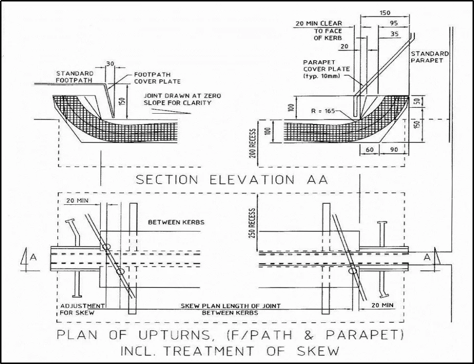
fIG 2
Alternative Designs
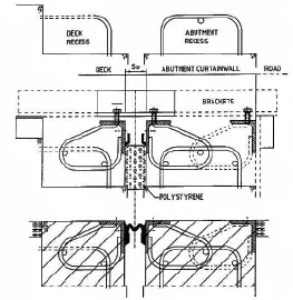
The design of the edge beams can be varied to suit local preferences and particular applications.
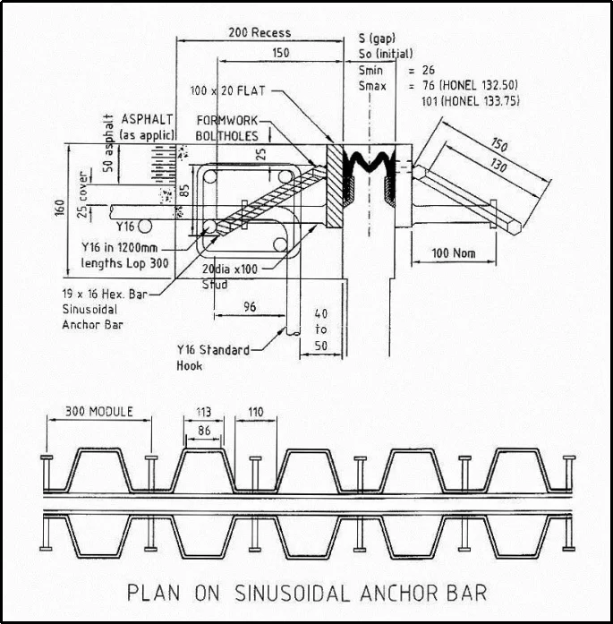
Fig: SINUSOIDAL ANCHOR BLADE DESIGN
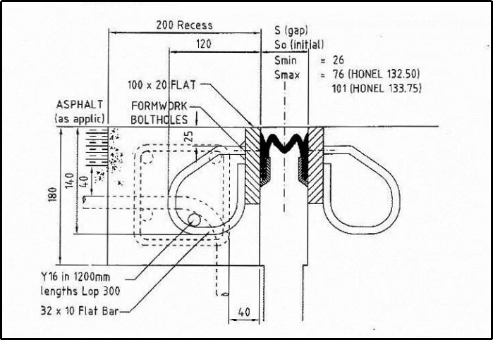
Fig: COMPACT CLOSED LOOP BLADE DISIGN
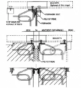
Installation Details
Method 1 - Two Recesses
Method 2 - No Recesses
CORROSION PROTECTION
SPECIFICATIONS
Movement
Longitudinal
Transverse
Vertical
80mm
60mm
±40mm
Reaction Forces
Fully Closed
Fully Opened
400N/m Compression
900n/m Tension
Weight
76 kg/m
Suggested Specification
1. Deck joints shall be fabricated from steel to AS 3679 Grade 250 (steel angles or flat bar blades, closed loop anchor bars and seal slot retainer) Hex bar anchors, Wherever applicable, shall be to AS 1443 Gr. S1214.
2. Steel angles, where provided, shall be drilled with vent holes at 300 crs to provide venting of air and moisture during concreting to permit adequate compaction of concrete behind the joints.
3. Upturns shall be provided at the junctions between curbs (or barriers) and deck which are usually the lowest point of the joint and hence the most likely point of leakage.
4. Welding shall be carried out to AS 1554 and, prior to galvanizing, all weld splatter shall be removed and the steelwork shall be grit blasted (to AS 1627.4 Grit Blast Class 2.5).
5. Galvanizing shall be carried out to AS 1650 but with a minimum zinc mass of 700g per m (approximately 100m thickness) after which all dags shall be removed and the individual lengths straightened to a tolerance of ±5mm over the entire length.
6. f.Joints shall be provided in (typically) six (6) metre modules, with bolted and dowelled water-tight connections.
7. Elastomeric seal elements shall be continuously extruded from CHLOROPRENE rubber, and shall be supplied and fitted in one continuous length (without joins).
8.The joints shall be fully assembled in the shop to confirm correct manufacturing drawings.
9. Angle-nosing joints shall be installed with the top leg of the angle parallel to the grade.
10. Completed joints shall be warranted against anchorage failure or dislodgment of the seal element for a period of 5 years from installation.
Types & Series: HERCULES (Heavy-Duty) FINGER JOINTS - HFJ Series
Hercules Finger Joints have been developed to fill the need for a heavy-duty expansion joint with large movement capacity. This type of expansion joint has been adopted as standard design for large movement expansion joint by many design authorities and government agencies worldwide because of their low & easy maintenance features.
Design Features & Advantages
Material
Installation
Method 1 - Installed in Concrete block out [preferred for cast in situ deck]
Method 2 - Installed WITHOUT Concrete block out [preferred for precast deck]
Maintenance
If maintenance requires replacement of membrane of finger plates, this can easily be carried out by de-tensioning the hold-down rods followed by removing 4-5 segments of finger plates in one lane and allowing traffic to continue using other lanes without causing congestion.
| Steel Nosing | HFJ/SN 100 | HFJ/SN 150 | HFJ/SN 200 | HFJ/SN 250 | HFJ/SN 300 | |
|---|---|---|---|---|---|---|
| Concrete Nosing | HFJ/CN 100 | HFJ/CN 150 | HFJ/CN 200 | HFJ/CN 250 | HFJ/CN 300 | |
| Tot. Movement (mm),# | 100 | 150 | 200 | 250 | 300 | |
| Nominal Dimensions (mm) | A | 120 | 170 | 220 | 270 | 320 |
| B | 110 | 110 | 150 | 150 | 200 | |
| C | 340 | 390 | 520 | 570 | 720 | |
| D | 390 | 440 | 570 | 620 | 770 | |
| E | 200 | 200 | 200 | 200 | 200 | |
| F | 400 | 400 | 400 | 400 | 400 | |
| G min. | 100mm or to Design Engineer’s Specification | |||||
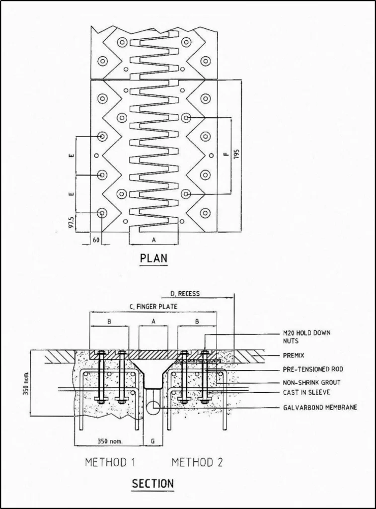
HERCULES FINGER JOINT
PART NO: HFJ/CN SERIES-CONCRETE NOSING
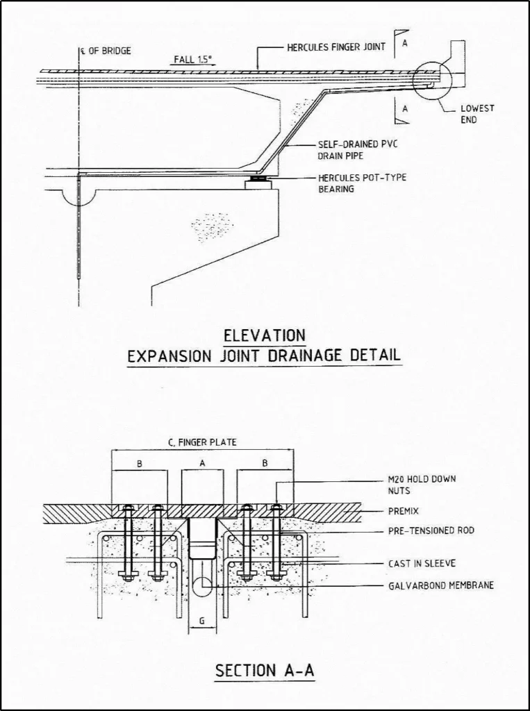
HERCULES FINGER JOINT
PART NO.: HFG/SN SERIES-STEEL NOSING
HERCULES SINUSOIDAL JOINT
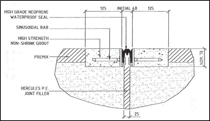
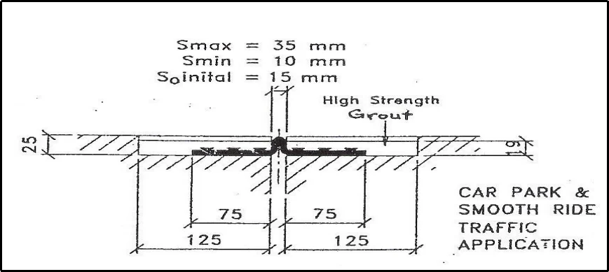
TYPE HRJ/25
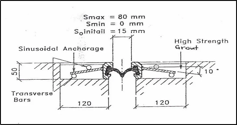
TYPE HSJ/80 (S.B.)
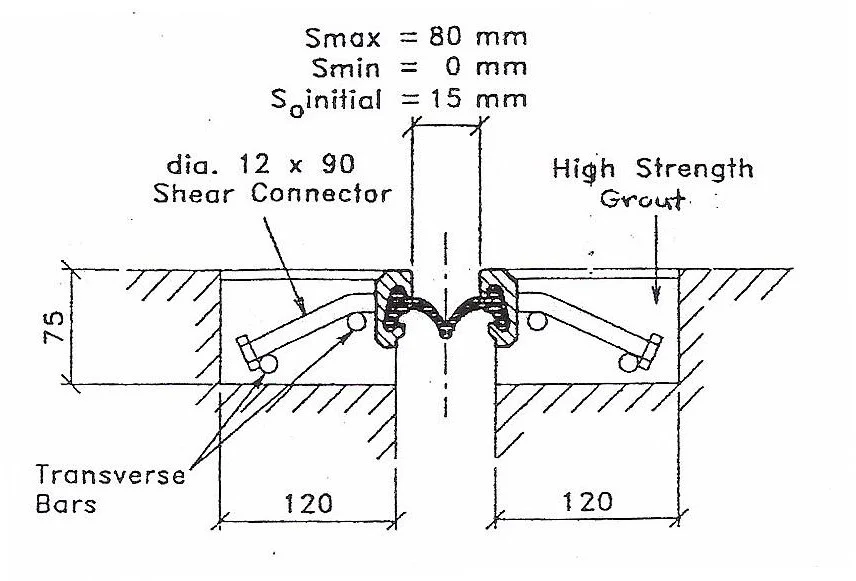
TYPE HSJ/80 (S.S.)
HERCULES RUBBER JOINT
| Hercules Part No. | Total Movement Capacity (mm) | Total Width (mm) |
|---|---|---|
| HRJ/100 | 100 | 390 |
| HRJ/150 | 150 | 430 |
| HRJ/200 | 200 | 800 |
| HRJ/230 | 230 | 950 |
| HRJ/300 | 300 | 1200 |
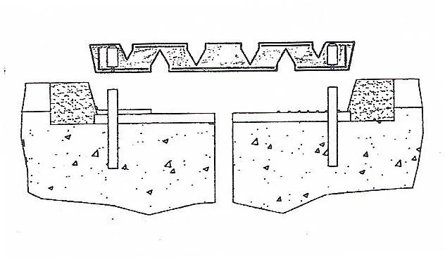
HERCULES ARCHITECTURAL EXPANSION JOINT
Hercules range of expansion joint also meets the requirement of architects. This includes joints designed to solve difficult problems with multi-directional movements and water-proofing requirements. Hercules engineers are capable of providing custom designed joints using many different materials e.g. Stainless Steel, extruded aluminum sections, brass and bronze with different finishes to meet all architectural requirements. All Hercules expansion joint systems can be incorporated with materials to provide fire protection.
Application: Car Park
Movement: Uni-directional horizonta
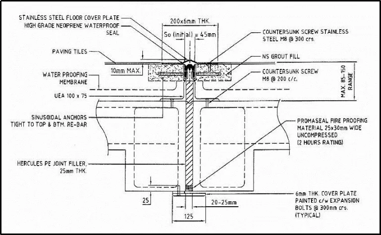
External Joint includes cover plates
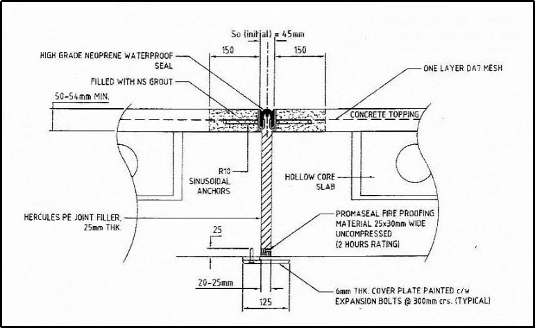
Internal joints excludes cover plates
Custom Designed
Application: Tower to Podium
Interfaces Movement: Multi-directional horizontal and vertical
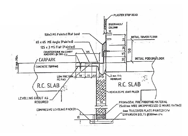
Galvanized M.S. angles / M.S. angles to required paint color system
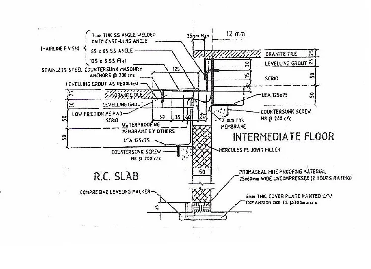
Stainless steel angles to required finish
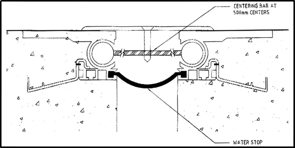
Sliding Aluminium Expansion Joint
Application: Retail Walkway (tiled)
Movement: Multi-directional horizontal, vertical, and rotational movements
HERCULES SINGLE ELEMENT BOLTED ALUMINIUM JOINT
Hercules Expansion Joint 'Type HAJ' is an aluminum deck joint which provides a light weight alternative to the heavier available steel designs. They can be used for heavy traffic on bridges, parking stations, access ramps and a variety of other applications.
Main Design Features
Austroads Clause 4.14 recommends a maximum gap of 100mm at the ultimate limit state. This is considered to be the maximum gap for providing a smooth and quiet ride. We propose that the joint be installed at time of maximum expansion to minimize the initial gap of the expansion joint.
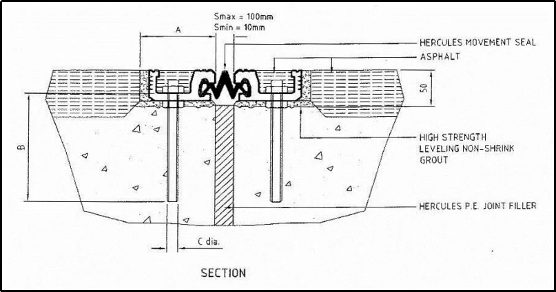
Material Specification
| Hercules Part No. | Total Movement (mm) | Dimension (mm) | ||
|---|---|---|---|---|
| A | B | C (Cast-in Bolts) | ||
| HAJ/25 | 25 | 100 | 150 | M16 Gr.8.8 AT 200 c/c |
| HAJ/50 | 50 | 100 | 150 | M16 Gr.8.8 AT 200 c/c |
| HAJ/75 | 75 | 100 | 150 | M16 Gr.8.8 AT 200 c/c |
| HAJ/100 | 100 | 100 | 150 | M16 Gr.8.8 AT 200 c/c |
HERCULES RUBBER JOINT (HRJ) SERIES
Structural Joint with Elastomeric Reinforced Panel System
HERCULES REINFORCED RUBBER JOINTS are designed according to UK Highways Agency Department standard BD33/94. The joint consists of elastomeric molded panel which are reinforced with internal reinforcement steel plates & sole plates. The elastomeric molded panel consists of chloroprene rubber which is resist to ozone & oil. The joints are supplied in standard module length and assembled between modules by tongued and grooved interlocking system. The panels to be bolted to the structural deck by using anchor bolts.
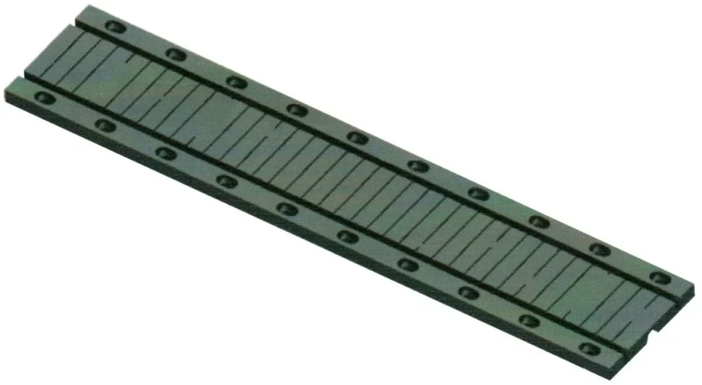
MATERIAL SPECIFICATION
| Material | Specification |
|---|---|
| Internal Reinforced & Sole Plates | BS 4360, ASTM A 36 or equivalent |
| Elastomeric Panels | Refer to Table 2. Material specification. |
| Bolts & Nuts | DIN 934, AASHTO M164 or equivalent |
INSTALLATION
The Hercules Reinforced Rubber Joint shall be designed to facilitate ease of installation and removal in the future without damaging any of the permanent bridge structure. The Reinforced Rubber Joint shall be installed according to manufacturer’s installation method statement.
Table 2 Physical Properties of Rubber
| Properties | Requirements | Test Method |
|---|---|---|
| Tensile Strength, kgs/cm² | 130 | ASTM D412 |
| Elongation at Break, % | 400% min. | ASTM D412 |
| Hardness, Shore ‘A’ | 60±5 | ASTM D2240 |
| Resistance to permanent set (After 22 hrs at 70°C)% | 30 max. | ASTM D395-89 Method B |
| Oil resistance, Immersion ASTM No.3 approximately 168 hrs at 25°C, Volume change % | 18 max. | DIN 53531 |
| Ozone Resistance (48 hrs at 38°C, 20% strain, 50 pphm in air) | No Cracks | ASTM D1149 |
| Low temperature brittleness, at 40°C | Not Brittle | ASTM D746 |
The Reinforced Rubber Joints designed for movement in the range from 50 mm. to 400 mm.
| Hercules Part No. | Total Movement (mm) |
|---|---|
| HRJ – 50 | 50 |
| HRJ – 65 | 65 |
| HRJ – 80 | 80 |
| HRJ – 100 | 100 |
| HRJ – 165 | 165 |
| HRJ – 230 | 230 |
| HRJ – 250 | 250 |
| HRJ – 260 | 260 |
| HRJ – 300 | 300 |
| HRJ – 400 | 400 |
Reinforced Rubber Joint System
Construction Details: HRJ -50, 65, 80, 100 & 165


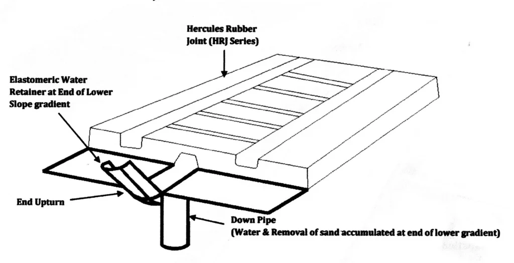
HERCULES Rubber Joint End details incorporated elastomeric retainer with upturn & down pipe for removal of sand normally accumulated at the end of lower gradient during downpour.
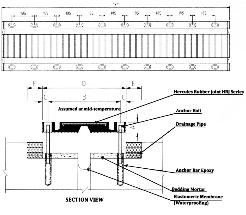
| Part No. | A,(mm) | B,(mm) | C,(mm) | D,(mm) | E,(mm) | X, Module Length (mm) |
|---|---|---|---|---|---|---|
| HRJ – 50 | 43 | 220 | 30 | 280 | 150 | 1865 |
| HRJ – 65 | 48 | 280 | 40 | 360 | 150 | 1865 |
| HRJ – 80 | 50 | 340 | 40 | 420 | 150 | 1865 |
| HRJ – 100 | 54 | 350 | 45 | 440 | 150 | 1865 |
| HRJ – 165 | 75 | 615 | 45 | 705 | 150 | 1865 |
| HRJ – 230 | 78 | 792 | 45 | 882 | 150 | 1865 |
| HRJ – 250 | 80 | 812 | 45 | 902 | 150 | 1865 |
| HRJ – 260 | 85 | 820 | 45 | 910 | 150 | 1865 |
| HRJ – 300 | 100 | 1036 | 55 | 1146 | 150 | 1250 |
| HRJ – 400 | 130 | 1300 | 55 | 1410 | 150 | 1250 |
RUBBER JOINT (HRJ) SERIES c/w Anti-Skid Plate
Structural Joint with Elastomeric Reinforced Panel System c/w Aluminum Anti-Skid Wear Plate
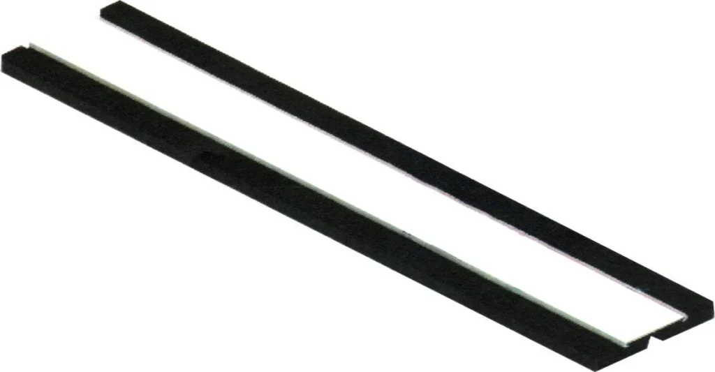
HERCULES REINFORCED RUBBER JOINTS C/W Aluminum Anti-Skid wear plate is designed to allow for expansion from 50 mm. to 165 mm. The joint consists of elastomeric molded panel which are reinforced with internal reinforcement steel plates & Aluminum Anti-Skid wear plate. The elastomeric molded panel consists of chloroprene rubber which is resist to ozone & oil. The joints are supplied in standard module length and assembled between modules by tongued and grooved interlocking system. The panels to be bolted to the structural deck by using anchor bolts.
MATERIAL SPECIFICATION
| Material | Specification |
|---|---|
| Internal Reinforced & Sole Plates | BS 4360, ASTM A 36 or equivalent |
| Aluminum Alloy 60661-T6 | ASTM B-221-73 |
| Elastomeric Panels | Refer to Table 2. Material specification. |
| Bolts & Nuts | DIN 934, AASHTO M164 or equivalent |
INSTALLATION
The Hercules Reinforced Rubber Joint shall be designed to facilitate ease of installation and removal in the future without damaging any of the permanent bridge structure. The Reinforced Rubber Joint shall be installed according to manufacturer’s installation method statement.
| Properties | Requirements | Test Method |
|---|---|---|
| Tensile Strength, kgs/cm² | 130 | ASTM D412 |
| Elongation at Break, % | 400% min. | ASTM D412 |
| Hardness, Shore ‘A’ | 60±5 | ASTM D2240 |
| Resistance to permanent set (After 22 hrs at 70°C)% | 30 max. | ASTM D395-89 Method B |
| Oil resistance, Immersion ASTM No.3 approximately 168 hrs at 25°C, Volume change % | 18 max. | DIN 53531 |
| Ozone Resistance (48 hrs at 38°C, 20% strain, 50 pphm in air) | No Cracks | ASTM D1149 |
| Low temperature brittleness, at 40°C | Not Brittle | ASTM D746 |

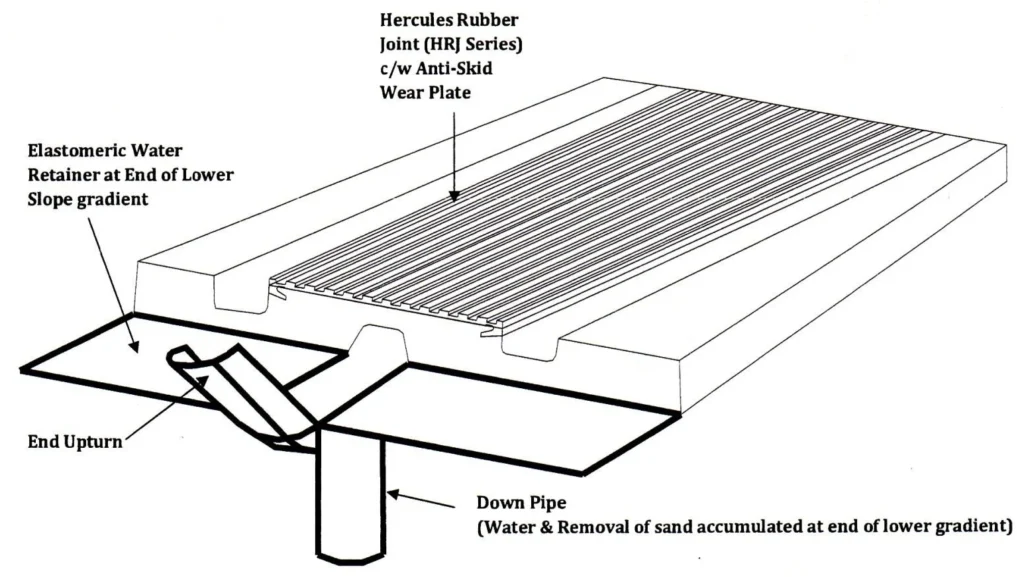
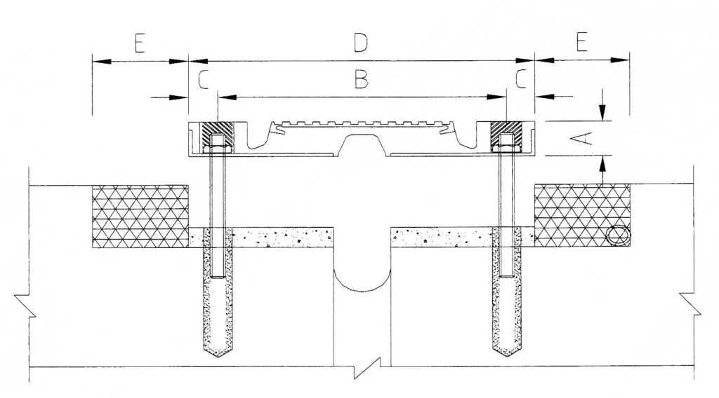
| Part No. | A,(mm) | B,(mm) | C,(mm) | D,(mm) | E,(mm) | X, Module Length (mm) |
|---|---|---|---|---|---|---|
| HRJ – 50 | 2 | 165 | 475 | 240 | 385 | 1865 |
| HRJ – 65 | 3 | 295 | 475 | 370 | 465 | 1865 |
| HRJ – 80 | 4 | 420 | 500 | 495 | 545 | 1865 |
| HRJ – 100 | 5 | 550 | 500 | 625 | 625 | 1865 |
| HRJ – 165 | 6 | 675 | 500 | 750 | 705 | 1865 |
ELASTOMERIC WATERSTOPS (HWS) SERIES
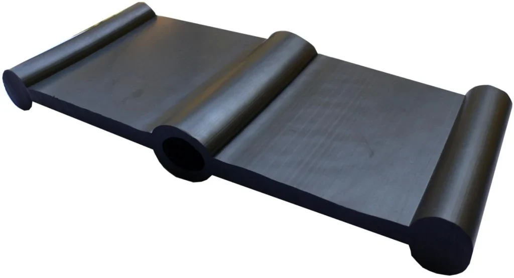
HERCULES RUBBER WATERSTOPS are available in two types, i.e. dumbbell & center bulb shaped. The waterstops are designed for joints in structures such as bridges & building. Hercules Rubber Waterstops are formed or extruded as a continuous piece. Any required intersection can be cold or hot vulcanized, as per site joining requirement.
MATERIAL SPECIFICATION
| Properties | Requirements | Test Method |
|---|---|---|
| Tensile Strength, Mpa | 17 Mpa min. | ASTM D412 |
| Elongation at Break, % | 450% min. | |
| Hardness, Shore ‘A’ | 60±5 | ASTM D2240 |
| Compression Set, (22 hrs at 70°C), % | 30% max. | ASTM D395-89 Method B |
| Ozone Resistance (24 hrs at 23°C, 5% strain, 10 ppm in air) | No Cracks | ASTM D1149 |
| Water Absorption (By Weight) 48 hrs at 70°C | 5% max. | ASTM D471-98 |
INSTALLATION
HERCULES waterstops can be pre-vulcanized to the required length and types of intersection prior to installation at site. Hot & cold vulcanizing can also be performed at site, if required.
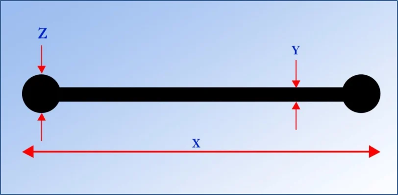
| Part No. | X, mm | Y, mm | Z, mm |
|---|---|---|---|
| HWS DB150 | 150 | 10 | 25.4 |
| HWS DB230 | 230 | 10 | 25.4 |
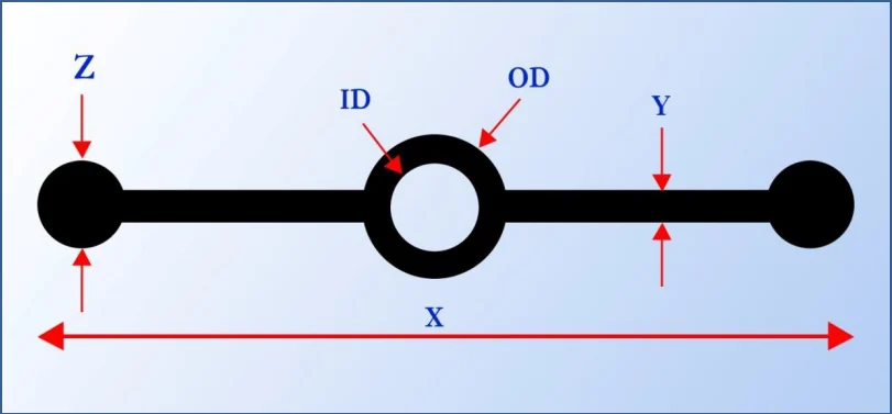
| Part No. | X, mm | Y, mm | Z, mm | ID, mm | OD, mm |
|---|---|---|---|---|---|
| HWS CB150 | 150 | 10 | 25.4 | 16 | 29 |
| HWS CB230 | 230 | 10 | 25.4 | 19 | 38 |
MODULAR JOINT (HMJ) SERIES
Structural Joint with Elastomeric Sealing System for large Movement
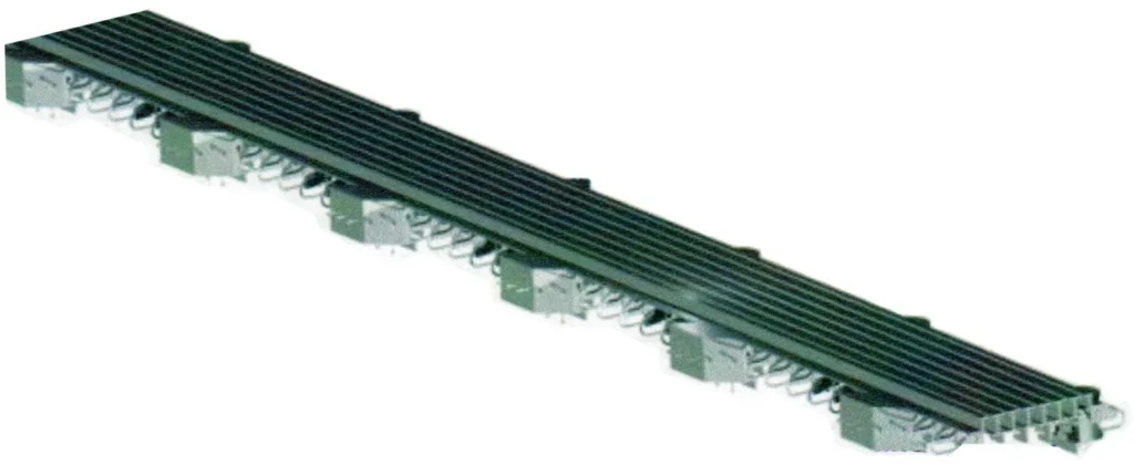
The HERCULES MODULAR JOINT consists of a modular with multiple elastomeric seal joint system. The seal shall consist of high grade preformed neoprene elastomeric seal which shall be assembled in place by steel edge and separation beams. For large movement, modular joint with swivel type support bars are utilized especially in the case of restricted space.
MATERIAL SPECIFICATION
| Material | Specification |
|---|---|
| Structural Steel | ASTM A588M, ASTM A572M Grade 345, ASTM A36M |
| Elastomeric Seal | Refer to Table 2. Material Specification. |
| Stainless Steel | ASTM A240 Type 304 |
| Polytetrafluorethylene (PTFE) | 100% virgin & conform to AASHTO LRFD |
| Bolts & Nuts | AASHTO M164 & AASHTO M298 (Galvanising) |
INSTALLATION
Hercules Modular Joint are designed to facilitate ease of installation and removal in the future without damaging any of the permanent bridge structure. The modular Joint shall be installed according to manufacturer’s installation method statement.
Table 2 Physical Properties
| Properties | Requirements | Test Method |
|---|---|---|
| Tensile Strength Mpa | 13.8 Mpa | ASTM D412 |
| Elongation at Break, % | 250% min. | |
| Hardness, Shore ‘A’ | 55±5 | ASTM D2240 |
| Compression Set, (70 hrs at 100°C),% | 40 max. | ASTM D395-89 Method B |
| Oil Swell, 70 hrs at 100°C weight change, % | 45 max. | ASTM D471 |
| Ozone Resistance (70 hrs at 90°C, 20% strain, 300 pphm in air) | No Cracks | ASTM D1149 |
| Over Aging 70 hrs at 100°C | ASTM D573 | |
| Change in Tensile Strength, % | -20 max. | |
| Change in Elongation at Break, % | -20 max. | |
| Change in Hardness | 0 to + 10 points |
The Modular Joint was designed for large movement in the range from 160 mm. to 880 mm.
| Hercules Part No. | Total Movement (mm) |
|---|---|
| HRJ – 160 | 160 |
| HRJ – 240 | 240 |
| HRJ – 320 | 320 |
| HRJ – 400 | 400 |
| HRJ – 480 | 480 |
| HRJ – 560 | 560 |
| HRJ – 640 | 640 |
| HRJ – 720 | 720 |
| HRJ – 800 | 800 |
| HRJ – 880 | 880 |
Sungle Support Bars Modular Joints System
Construction Details
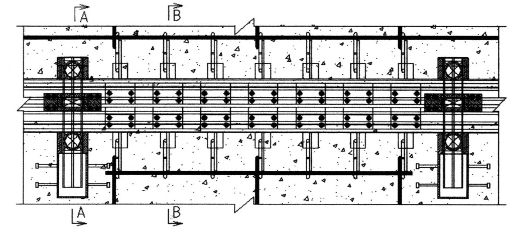
PLAN VIEW
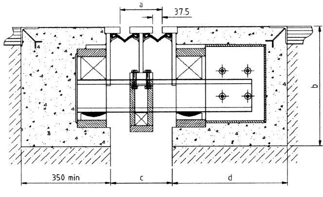
SECTION A – A
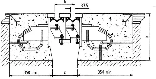
SECTION B – B
| Part No. | No. of Seals | A, (mm) | B, (mm) | C, (mm) | D, (mm) |
|---|---|---|---|---|---|
| HRJ – 160 | 2 | 165 | 475 | 240 | 385 |
| HRJ – 240 | 3 | 295 | 475 | 370 | 465 |
| HRJ – 320 | 4 | 420 | 500 | 495 | 545 |
| HRJ – 400 | 5 | 550 | 500 | 625 | 625 |
| HRJ – 480 | 6 | 675 | 500 | 750 | 705 |
| HRJ – 560 | 7 | 805 | 500 | 880 | 785 |
| HRJ – 640 | 8 | 930 | 550 | 1005 | 865 |
| HRJ – 720 | 9 | 1060 | 550 | 1135 | 945 |
| HRJ – 800 | 10 | 1185 | 550 | 1260 | 1025 |
| HRJ – 880 | 11 | 1315 | 550 | 1390 | 1105 |
Swivel Support Bars Expansion Joint System
Construction Details

PLAN VIEW
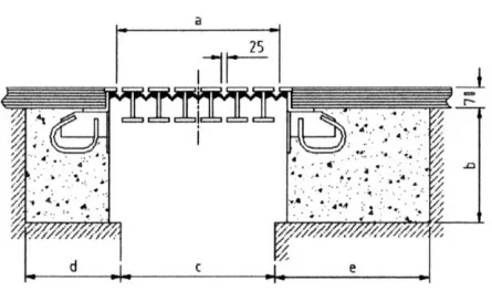
SECTION AT ANCHORAGE
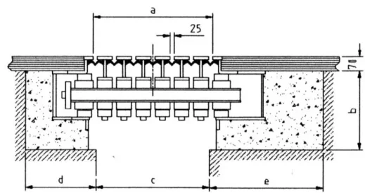
SECTION THROUGH SUPPORT BOX
| Part No. | No. of Seals | A, (mm) | B, (mm) | C, (mm) | D, (mm) | E, (mm) |
|---|---|---|---|---|---|---|
| HRJ – 160 | 2 | 155 | 425 | 120 | 355 | 410 |
| HRJ – 240 | 3 | 275 | 435 | 230 | 385 | 460 |
| HRJ – 320 | 4 | 395 | 450 | 305 | 395 | 510 |
| HRJ – 400 | 5 | 515 | 455 | 415 | 410 | 565 |
| HRJ – 480 | 6 | 640 | 465 | 525 | 415 | 630 |
| HRJ – 560 | 7 | 760 | 480 | 640 | 425 | 690 |
| HRJ – 640 | 8 | 875 | 485 | 745 | 440 | 750 |
| HRJ – 720 | 9 | 1000 | 500 | 860 | 445 | 810 |
| HRJ – 800 | 10 | 1115 | 505 | 965 | 455 | 870 |
| HRJ – 880 | 11 | 1230 | 510 | 1070 | 460 | 920 |
COMPRESSIVE ELASTOMERIC SEAL (HRSJ) SERIES
HERCULES COMPRESSIVE ELASTOMERIC SEAL (HRSJ) are manufactured from chloroprene rubber which is specially designed to resist ozone and oil. The compression seal is specially designed with two lateral flaps 50 mm. wide/each to allow anchorage to the existing concrete. The center multi-celled body specially designed to absorb impact load associated with such as parking deck applications.
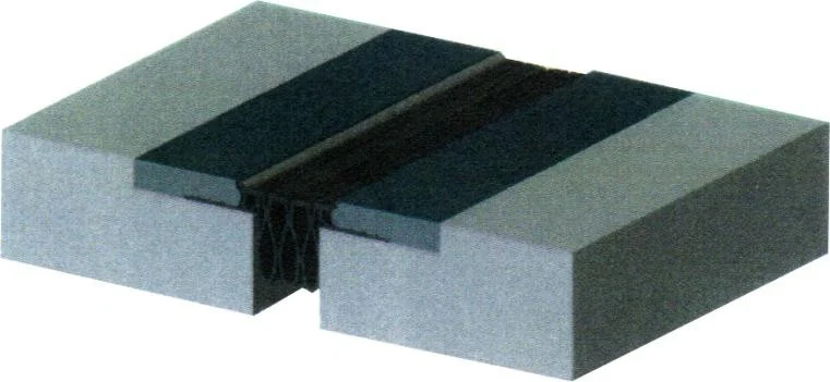
MATERIAL SPECIFICATION
| Properties | Requirements | Test Method |
|---|---|---|
| Tensile Strength Mpa | 17 Mpa. Min. | ASTM D412 |
| Elongation at Break, % | 450% min. | |
| Hardness, Shore ‘A’ | 60±5 | ASTM D2240 |
| Compression Set, (22 hrs at 70°C),% | 30 % max. | ASTM D395-89 Method B |
| Ozone Resistance (24 hrs at 23°C, 5% strain, 10 pphm in air) | No Cracks | ASTM D1149 |
| Water Absorption (By Weight) 48 hrs at 70°C | 5% max. | ASTM D471-98 |
INSTALLATION
Installation methods may vary depending on job requirements. Details installation method statement provided separately upon depending on job requirements.
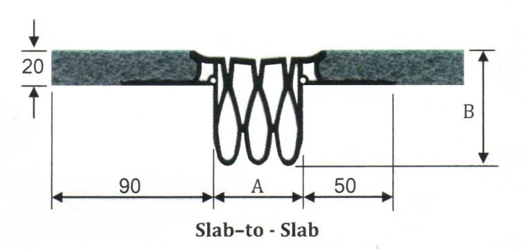
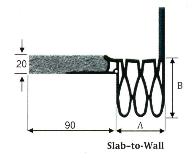
| HRSJ-S | Total Movement | Joint Opening “A” | “A” | Depth “B” | |||
|---|---|---|---|---|---|---|---|
| Thermal Min. | Thermal Max. | Safety Max | Min. | Max. | Clearance | ||
| 20 | 20 | 10 | 23 | 30 | 30 | 11 | 55 |
| 35 | 35 | 15 | 40 | 48 | 22 | 35 | 58 |
| 65 | 65 | 20 | 65 | 84 | 33 | 58 | 65 |
| 85 | 85 | 25 | 90 | 110 | 40 | 85 | 60 |
| 100 | 100 | 38 | 112 | 140 | 55 | 106 | 55 |
| 125 | 125 | 38 | 140 | 165 | 75 | 133 | 58 |
DIMENSION – SLAB – TO – SLAB
| HRSJ-W | Total Movement | Joint Opening “A” | “A” | Depth “B” | |||
|---|---|---|---|---|---|---|---|
| Thermal Min. | Thermal Max. | Safety Max | Min. | Max. | Clearance | ||
| 20 | 20 | 10 | 23 | 30 | 30 | 11 | 55 |
| 35 | 35 | 15 | 40 | 48 | 22 | 35 | 58 |
| 65 | 65 | 20 | 65 | 84 | 33 | 58 | 65 |
| 85 | 85 | 25 | 90 | 110 | 40 | 85 | 60 |
| 100 | 100 | 38 | 112 | 140 | 55 | 106 | 55 |
| 125 | 125 | 38 | 140 | 165 | 75 | 133 | 58 |

